++ ++
Project / Startup — Hardware & Firmware

Tachyon -- Velocity-Based Training, Made Accessible

An IMU-based velocity-based-training (VBT) device and app, built with two co-founders as my first real startup attempt. VBT is currently locked behind expensive, complicated equipment aimed at elite athletics and pro lifting labs. Tachyon's whole premise is that an average lifter chasing progressive overload deserves the same feedback loop - so we're building a bar-mounted IMU that streams live rep data to a phone, with zero setup fuss.
RoleFirmware & Hardware / Co-founder
Team3 Duke students, founding team
TimelineSpring 2026 - Present
StatusV1 PCB built - entering testing phase
IMU Sensor FusionProduct DevelopmentPCB DesignKiCADApp Development
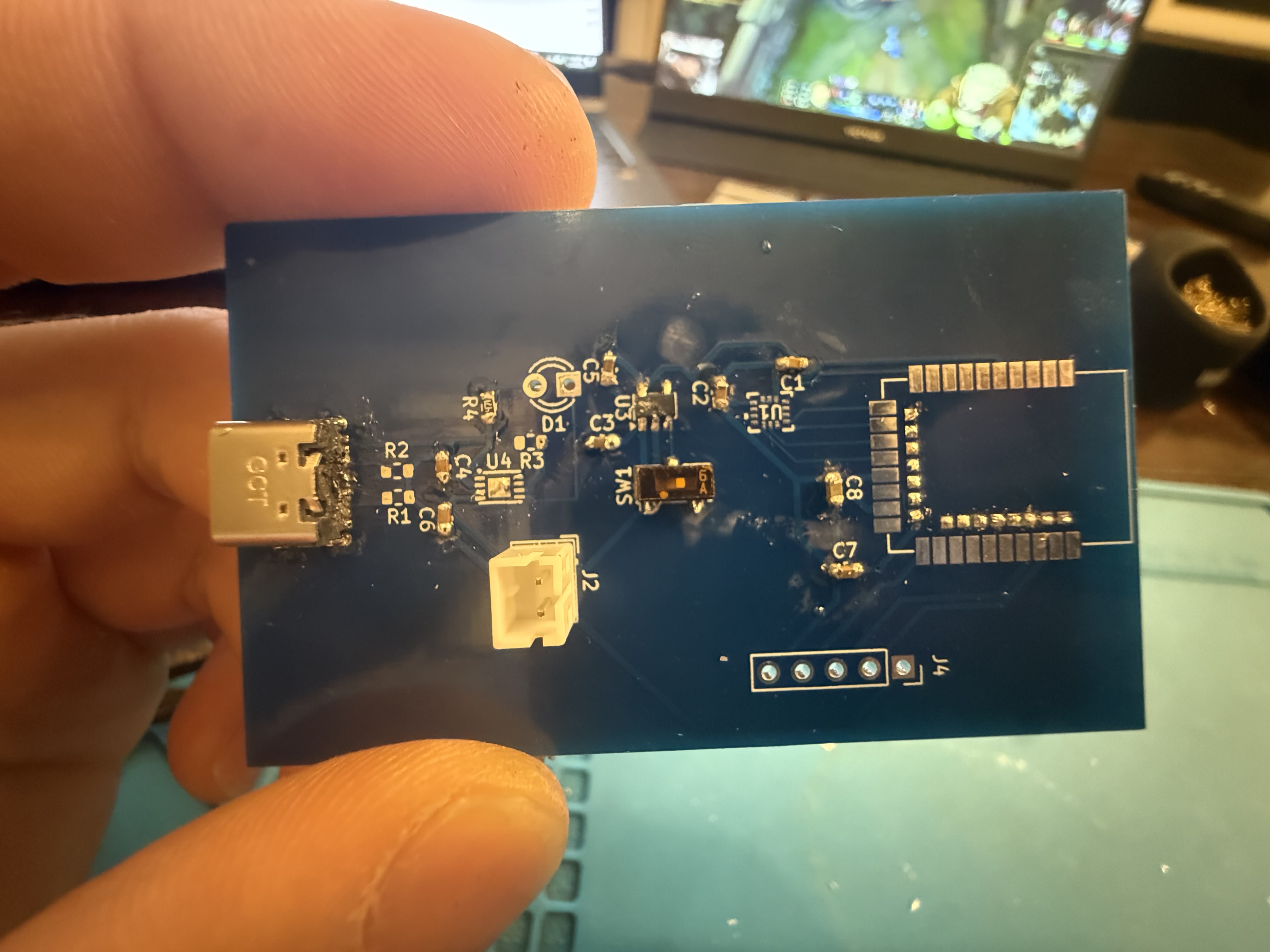
Tachyon V1 assembled PCB
Tachyon V1 — assembled PCB
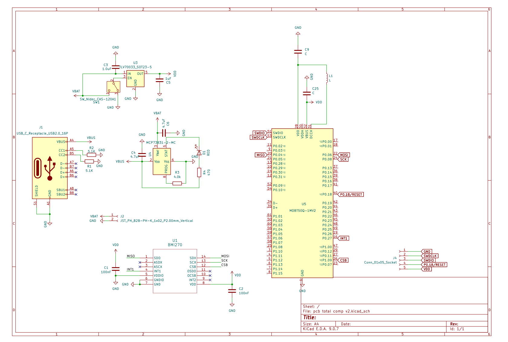
Tachyon V1 schematic
V1 schematic — MCU, IMU & Power Distribution

Our mission

Velocity-based training is one of the most useful tools in strength and conditioning: bar speed tells you, rep by rep, whether you're actually training the quality you intend to (max strength, power, hypertrophy) instead of guessing off a instinct. Today it lives almost entirely in university sports-science labs and professional weight rooms: linear position transducers and optical systems that cost hundreds to thousands of dollars, need to be clamped to a rack, cabled to a laptop, and calibrated before every session.

Our mission is to take the underlying value of VBT; knowing your velocity, knowing when a set stops being productive, knowing how much load to add or take off, and put it in the hands of the average lifter, not just the athletes and labs that can afford commercial gear. Tachyon is our attempt at that: an IMU that clips onto the bar, a firmware stack that turns raw accelerometer and gyro data into an accurate rep velocity, and an app that tells you when to rack the bar and what to load next.

Simplified Proposed System

Physical bar motion
eccentric ↕ concentric
The puck moves with the bar through the full rep.
01Sample Accel + Gyro
02Filters
03Integration
04Detect Rep + MCV
05Reset @ Rest
00Calibration
BMI270 →
→ BLE
nRF52833real-time
firmware loop
Live training feedback
0.67
m/s · MCV
Keep Going / Stop & Load Suggestion
Power backboneUSB-CMCP7381 charger250 mAh LiPoTLV70033 · 3.3 VMCU + IMU
Bar moves → IMU senses → firmware continuously filters, integrates, detects and resets → rep velocity is sent to the app. Then the loop repeats on the next rep.

What we're optimizing for, and where we stand

Here's what we're holding ourselves to, and where we currently stand on each.

Setup timeBy design

Clip the device on the bar, and have your phone handy - thats it!

Velocity accuracyBiggest open question

The estimate needs to hold up against a commercial reference, not just look clean in isolation (see Section 06).

CostTargeting sub-lab pricing

Priced for an individual lifter, not a university sports-science budget. V1 is currently about $30–40 in prototype hardware, using primarily single-unit DigiKey pricing; this is intentionally conservative and should fall with volume sourcing and PCB scale.

V1 prototype BOMSingle-unit pricing based primarily on DigiKey + estimated passives and small-quantity PCB fabrication
~$30–40
Battery lifeEstimated 70–100 hours

A 250 mAh LiPo and an estimated ~2.1 mA active draw give ~95 hours after a conservative 20% capacity derating, so V1 is designed around roughly 70–100 hours of continuous active use.

Turning raw IMU noise into a rep, from scratch

Turning raw accelerometer data into a trustworthy velocity number is the hard part of this project, and we built the rep-detection and filtering pipeline ourselves.
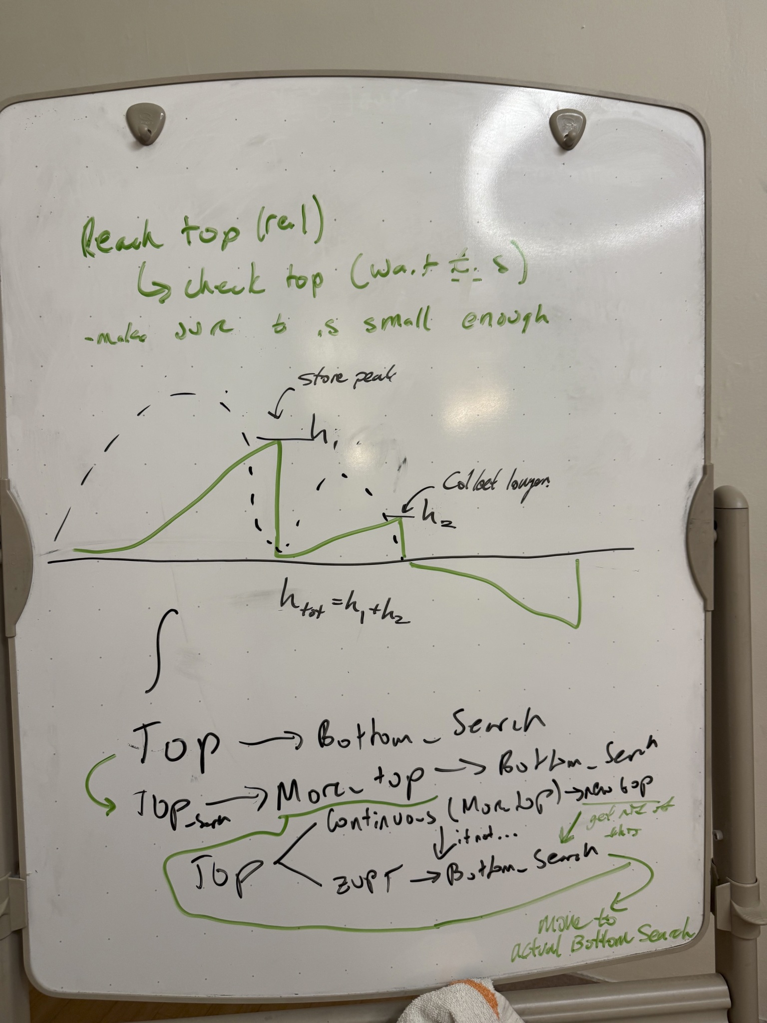
Whiteboard session developing Tachyon rep detection logic
Early whiteboarding of the rep-detection state machine.
01 / Rep detection

First, we had to define what a rep actually looks like to an IMU.

Reliable rep detection meant translating the biomechanics of a lift into something the IMU could recognize. We broke down our own reps into distinct phases - rest, descent, direction change, concentric motion, and return to rest - then used those patterns to define the state transitions and thresholds needed to detect real reps while rejecting noise and unintended movement.

REST ECCENTRIC BOTTOM CONCENTRIC PEAK REP END
06 / From whiteboard → working test

Then I put the algorithm on actual hardware.

For early testing, I strapped the IMU and MCU to a water bottle and recorded squat-like repetitions while streaming the sensor data. It was a rough setup, but it gave us a repeatable physical input for debugging the full signal-processing pipeline.
IMU + MCU strapped to a water bottle while running squat reps of different edge cases (Pause Reps, Super Fast Reps, etc.).
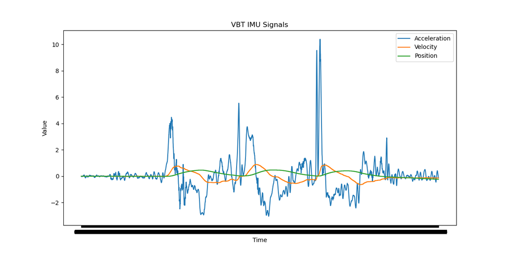
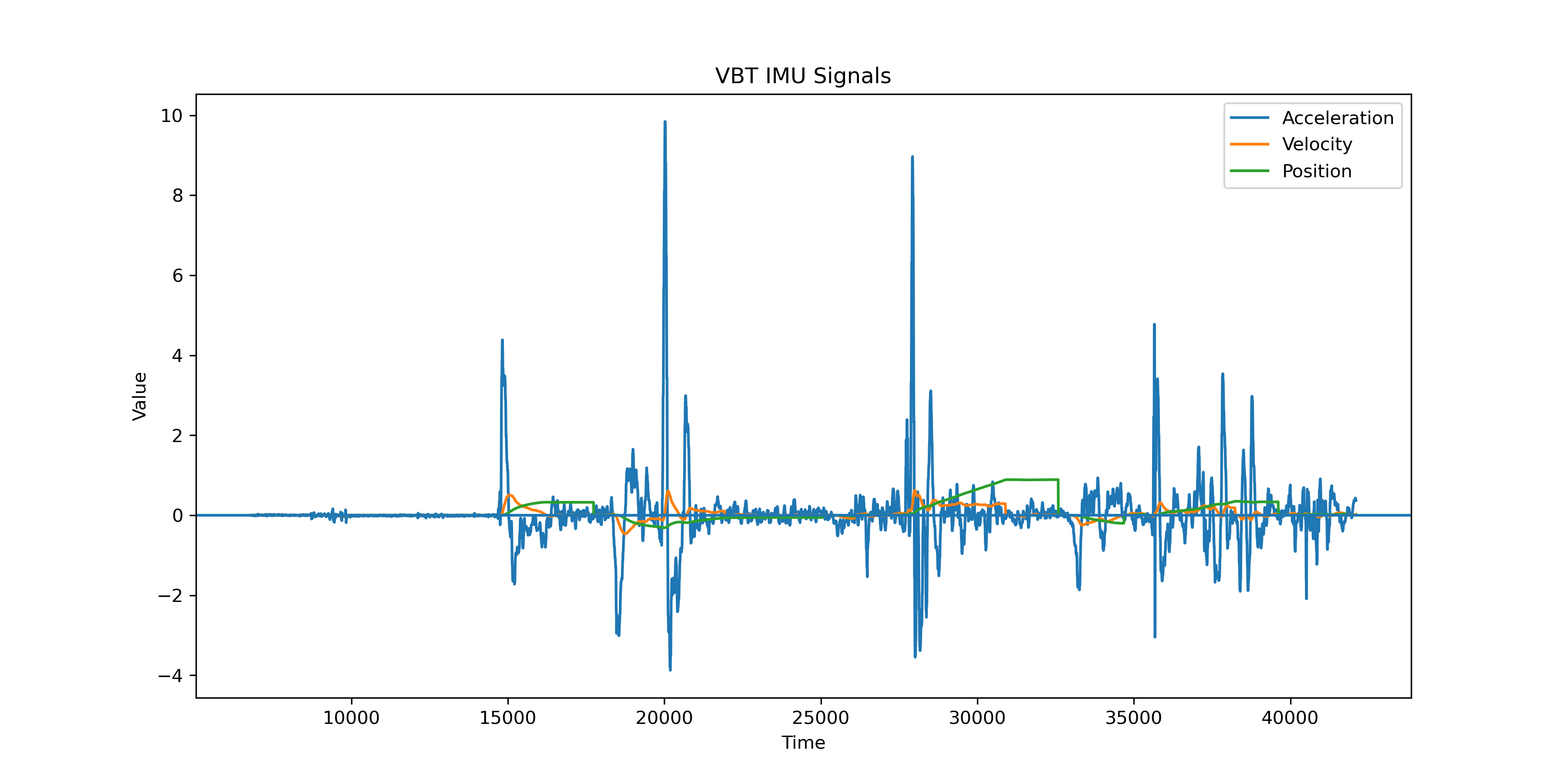
Early Pipeline Early IMU processing pipeline showing residual position drift
Initial filtering + strapdown integration — rep motion is visible, but lacks a baseline; will lead to drift accumulation.
Current Pipeline Current IMU processing pipeline with ZUPT and rep detection logic
Expanded pipeline with ZUPT and rep-detection logic; stationary periods are identified and used to constrain accumulated integration drift.

These traces show the progression of the firmware rather than an unfiltered “before” and filtered “after.” The early pipeline already applied basic filtering before integrating acceleration into velocity and position, but small errors still accumulated across successive reps. As the algorithm developed, we added more deliberate filtering alongside zero-velocity update (ZUPT) logic and rep detection. Detecting when the device is stationary gives the firmware opportunities to reset the velocity estimate, limiting how much integration error carries from one rep into the next. The result is a much more stable position estimate while still preserving the motion of each rep.

From working prototype to validated numbers

So the state of the project: hardware is built and stable, and we have a firmware and filtering pipeline that we designed and debugged ourselves and that visibly cleans up the raw signal. What we don't have yet is proof that the resulting velocity number is accurate, clean-looking is not the same as correct, and that's the next milestone.

We're setting up a side-by-side benchmark against a commerical system (Perch), working with the Duke Athletics weight room to compare Tachyon's live output against a Perch VBT system on the same reps. That comparison is what will tell us whether our velocity is close enough to trust, or whether it sends us back to the filtering pipeline before we touch housing or app polish.

🚧 In construction

Benchmarking Tests Soon: Housing, PCB Revisions, and App Logic Follow From The Results.

V1 Bill of Materials

This BOM estimates the cost of building a single V1 Tachyon prototype. Component prices are based primarily on the small-quantity / single-unit prices I used from DigiKey. The nRF52840 module was sourced separately from SparkFun. These prices are useful for estimating prototype cost, but they are not representative of a production BOM because most electronic components become cheaper when purchased in quantity.

I kept the breakdown focused on the major cost-driving parts rather than listing every resistor and capacitor. Low-cost passives and miscellaneous support components are grouped into one estimate, and I separately include an allowance for small-quantity PCB fabrication so the total better represents the actual cost of producing one working board.

PartFunctionQtySourcePrototype cost
MCP73831-2-MCLiPo charging IC1DigiKey ↗$0.79
TLV70033DDCR3.3 V regulator1DigiKey ↗$0.85
B2B-PH-K2-pin JST battery connector1DigiKey ↗$0.11
3.7 V, 250 mAh LiPoBattery1DigiKey ↗$6.95
USB-C receptacleCharging / power input1DigiKey ↗$0.78
BMI2706-axis IMU1DigiKey ↗$3.73
MDBT50Q-1MV2nRF52840 BLE MCU module1SparkFun ↗$8.95
LQM21DN100M70LVDDH inductor1DigiKey ↗$0.19
CAS-120TAPower switch1DigiKey ↗$1.29
Passives + support partsResistors, capacitors and miscellaneous componentsEstimated~$1–2
Custom PCBSmall-quantity V1 board fabrication1Estimated~$5–10
Estimated V1 prototype hardware cost~$30–40 / unit

The specifically priced electronic parts total approximately $23.64. Adding roughly $1–2 for passives and support components and approximately $5–10 for small-quantity PCB fabrication puts the practical V1 prototype cost at roughly $30–40 per device.

This is deliberately a prototype estimate rather than a target manufacturing cost. Buying one or a handful of parts from distributors such as DigiKey carries much higher per-unit pricing than volume purchasing. PCB fabrication also has setup and shipping costs that are spread across very few boards at this stage. As Tachyon moves toward later revisions, quantity pricing, PCB panelization/assembly, and component substitutions provide clear opportunities for cost reduction.

Why 70–100 hours?

For Tachyon, I selected a 250 mAh, 3.7 V LiPo to keep the device compact while still providing enough capacity for multiple training sessions. The battery supplies the TLV70033 3.3 V regulator, which powers the microcontroller and BMI270 IMU.

To estimate battery life, I added the expected current draw of each major component. The BMI270 draws approximately 0.97 mA with the accelerometer and gyroscope operating in performance mode. MCU consumption varies because the processor and BLE radio are not active continuously, so I estimated approximately 1.00 mA average for processing and BLE communication. I also included approximately 0.13 mA for the regulator and other miscellaneous losses.

BMI270 (accel + gyro): 0.97 mA
MCU + processing + BLE: ~1.00 mA
Regulator + miscellaneous: ~0.13 mA
────────────────────────
Itotal ≈ 2.1 mA

Using the full 250 mAh battery rating, the theoretical runtime is:

t = 250 mAh / 2.1 mA ≈ 119 hours

However, I did not expect the full rated capacity to be usable. LiPo voltage decreases as the cell discharges, while the electronics require a regulated 3.3 V supply. I therefore applied a conservative 20% derating, giving approximately 200 mAh of usable capacity.

Usable capacity ≈ 250 mAh × 0.80 = 200 mAh
trealistic = 200 mAh / 2.1 mA ≈ 95 hours

Based on this estimate, I designed around approximately 70–100 hours of continuous active operation per charge rather than relying on the theoretical maximum. This remains an engineering estimate; measured runtime will depend on the final BLE duty cycle, firmware behavior, regulator losses, and actual battery capacity.